

An aerial view of the abandoned #7 Mine complex, circa 1937

Winter view of the Mine #7 incline plane.
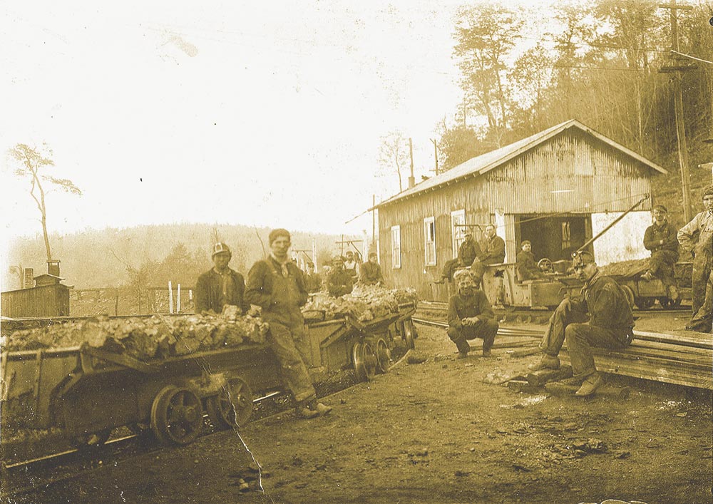
Penn Mary #7 Mine (circa 1914)

Frank Rosmus, motorman working at Mine #7 (circa 1912-28)
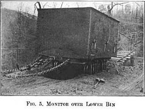
Coal monitor (car)
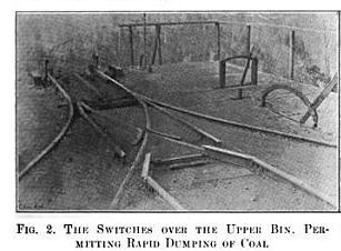
Switches over the upper bin
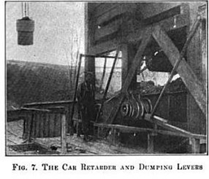
Car retarder and dumping levers
1912-1928
Due to the significant elevation difference between where the mine drifts were located and the loading tipples at the railroad, a different system for coal transport had to been employed. This system was known as an incline plane (see photos).
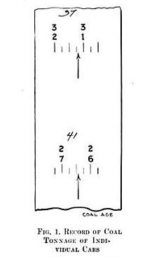
Tape used to record the weight of an individual coal car.
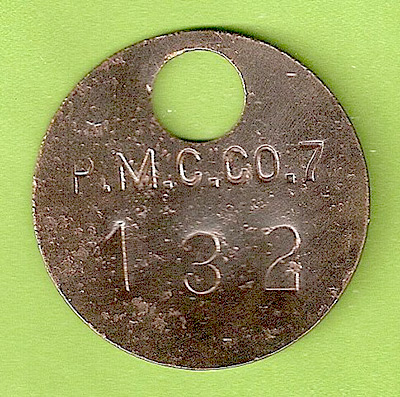
Penn Mary mine check

Hangar that held the wire providing power to the Mine #7 trolley motors (found Summer 2010)

Spikes from the Mine #7 incline plane / main haulage track (found Summer 2010)

Piece of coal found in a boney dump near Mine #7
Once the loaded mine cars left either of the mine openings, they were placed by a motorman onto tracks leading to the dumping point at the tipple (see photo). There, each car passed over a scale, which weighed it and automatically recorded the weight onto a tape (see photo). The weigh man then took the mine check (see photo) that was attached to the car by the miners who had loaded it, and transferred the number stamped on the check to the tape. These tapes were taken to the mine office at day’s end for calculation of each miner’s paycheck.*
Once weighed, the mine cars were then dumped into the upper bin of the tipple (which could hold 43 tons), and in turn funneled into a steel “monitor” (railroad car) positioned directly below the bin (see photo). The empty mine cars were then routed from the dumping track to side tracks for return to the mines (see photo). When the monitor was completely loaded, it moved through a switch and down one side of the incline, attached to a steel cable. While doing so, it drew upward a similar monitor from the lower dumping point, on the opposite track and through the switch to replace itself. With only one switch at the top of the incline, each monitor only went through the switch to be loaded, and then back through the switch again to be unloaded.
As the monitor moved down the incline**, the speed of the descent was controlled by two sheaves (see photo). These sheaves were wrapped by the steel cable in a figure-of-eight pattern, making good contact. Two brake bands, one on each sheave, restrained both the sheaves and the rope when the brake was applied by the operator at the bottom of the incline, keeping both cars under control.
When the monitor reached the bottom of the incline, it dumped into the 50-ton lower bin. With the railroad tracks set at a 2% grade beneath the lower tipple, the miner stationed at the side of the tipple could easily load and move the hopper cars utilizing a car retarder (see photo).
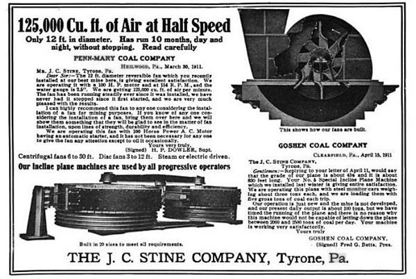
Ad for an incline plane machine
*When the Heilwood mines were unionized under the UMWA, a union member would be appointed as the weighman to determine the exact weight of the car and not a coal company personnel.
**The steepest grade is 38% with grades near the top from 20-25% and a grade of 8% approaching the dumping point at the lower end.